Eric Kim
Custom Screw Conveyor
Screw Conveyor Purpose
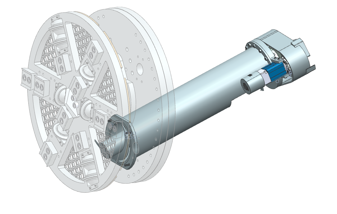
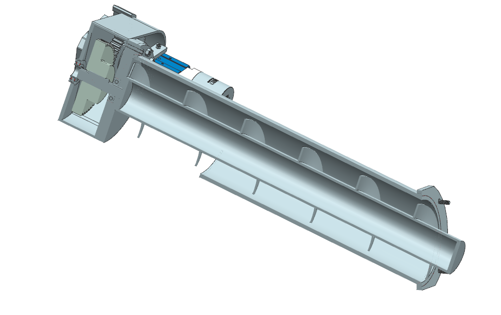
Also known as an auger, this was the primary method of transporting soil from the front of the tunnel boring machine to the rear. This is to make way for more soil that will get excavated and have a continuous cycle of excavating and storing dirt. Because our soil has no treatment or water added, it will be very coarse and abrasive rock (based on the Las Vegas soil conditions).
Design Process
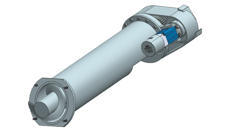
General dimensions of this auger were chosen from literature. The auger uses an archimedes screw with specific inner and outer diameters for the rock sizes and shapes we would be encountering. There were a lot of spacing and sizing issues with the auger because it had to pass through many subsystems. Namely, the hydraulic fittings and motors and the steering joints were all regularly changing and intefering during the design process. It required conveying the correct auger length and angle to these responsible engineers.
Analysis

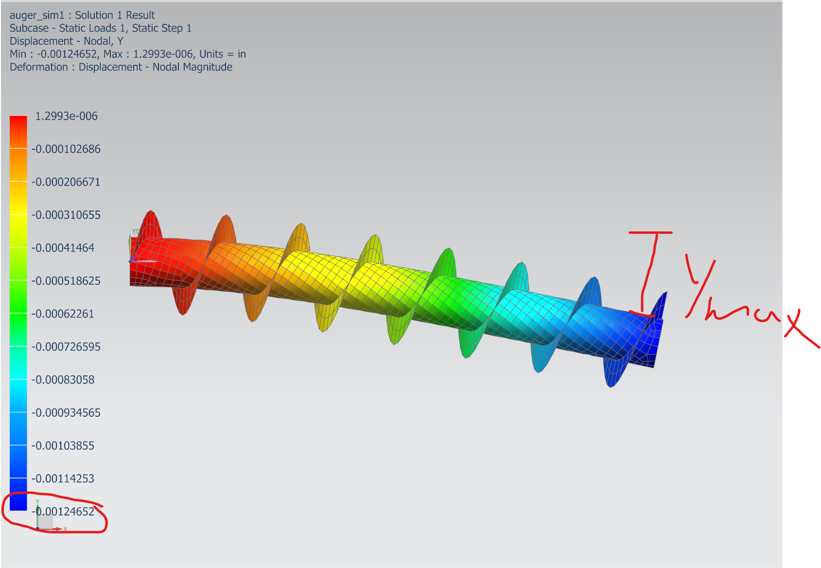
Deflection on the auger bit itself was done to ensure it would not interfere with the casing. Additionally, the flights of the screw portion were looked at for shear failure and bending stress.
Manufacturing
Welding and machining the steel components were done out of house, with drawings that had tolerances and instructions that were important to the functionality of the auger. The hardest weld to describe to manufacturers was the elliptical weld for the plate that this whole assembly was mounted to. The casing came off a vertical wall at an angle, and the casing would be mounted to the wall via a welded plate. For both the plate and casing to interface, there had to be a circular, angled opening for the casing to be welded on.
Tolerances on hole position were used the most. The screw portion of the auger needed to be centered so it would not interfere with its circular housing, so a positional tolerance on the bearing location was used. Additionally, radial patterns of fasteners shared tolerances so that all fasteners could be mounted without causing interference on their respective parts.


